TECHNICAL SPECIFICATIONS FOR GE - IS210TREAS1A
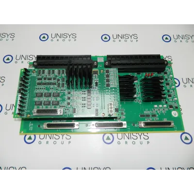
IS210TREAS1A is an Aero Derivative Turbine Emergency Trip Board manufactured and designed by General Electric as part of the Mark VIe Series used in distributed control systems. As a component of the Mark* VIe system, the Aero derivative Turbine Emergency Trip (TREA) terminal board and WREA option card work with PPRA turbine I/O packs. The following are the inputs and outputs:
Two 24-point pluggable barrier terminal blocks (H1A or S1A) or 48 pluggable Euro-style box terminals are used as customer input terminals (H3A or S3A).
Six fanned passive pulse rate sensors that sense a toothed wheel to determine the turbine speed (up to three shafts with two sensors each).
To trip the system, three solid-state output contacts with TMR votes of TREAH1A, H3A plus WREAH1A or TREAS1A, S3A plus WREAS1A must be 24 V dc.
Four voltage detecting circuits for 24-125 V dc voltage for trip string monitoring.
Four extra hardware or conditional trip inputs are provided via four 24 V dc WREAH1A or WREAS1A contact inputs. On WREA, wetting power is supplied via the JH1 connector.
Using an RS-232 or RS-422 transmitter, one-speed repeater output for each of the six-speed inputs duplicates the speed pulse rate signals.
INSTALLATION:
The WREA should by default be mounted to the TREA terminal board when it is received from the factory. Use the steps below to replace the WREA if the board needs to be taken out to service the TREA fanning jumpers.
Align the WREA's two connectors with the TREA's two connectors. When viewing the WREA, the row of configuration jumpers at the bottom of the board is regarded as the end.
After the two boards are in line, firmly press on the four screw heads that surround the connector to secure it.
Voltage detection, trip contact inputs, and relay outputs are connected to the I/O terminal blocks TB1 for the H1 and S1 board variations. TB2 is wired with passive pulse rate pick-up devices. Each block has 24 terminals that may accommodate wires up to #12 AWG and are secured with two screws. Each terminal block is followed by a shield termination strip connected to the chassis ground.
Voltage detection, trip contact inputs, and relay outputs are attached to the I/O box terminals at the top of the board for the H3 and S3 board variations. The lower terminals are coupled with passive pulse rate pick-ups. Each terminal accepts a single #12 AWG wire and plugs it into a header on the TREA board.
OPERATION:
Three PPRA I/O packs placed directly on the TREA board are intended to be used with it. A self-contained emergency trip function is therefore formed by the TREA/WREA/PPRA assembly. Only three PPRA I/O packets are necessary for TREAH1A, S1A, H3A, and S3A plus WREA to operate properly. Operation with a single or twin pack is not feasible. In systems with a single controller, the controller R network, S network, and T network should be linked to the PPRA on the JX1 connection, JY1 connector, and JZ1 connector, respectively. Keep in mind that one controller is the source of all three networks. The R network of the controller should be connected to the PPRA on the JX1 connector, the S network to the PPRA on the JY1 connector, and both the R and S networks to the PPRA on the JZ1 connector in systems with dual controllers.
CONFIGURATION:
The fanning of the X channel speed inputs to the Y and Z PPRA I/O packs is selected by jumpers JP1 and JP2. These jumpers are required for TREA and WREA operations with PPRA. The six-speed repeater output circuits' output behavior is configured using the WREA jumpers JP1 through JP12. RS-232 signal level (the default) and RS-485 signal level can be chosen for the repeater output using the jumpers JP1 through JP6. While JP4?JP6 configure repeaters for PR4?PR6, JP1?JP3 configure the repeater outputs for PR1?PR3. When used with PPRA, jumpers JP7 through JP12 should stay in the PR1 through PR6 positions by default.