Repair and Testing of circuit boards to diagnose ensure functionality to maintain current inventory and retain obsolete circuit boards/modules.
Training
Controls including HMI Training for Engineers, Technicians and Operators with wide variety of practical equipment including Management and Health & Safety.
Purchase
You upgrade equipment and we purchase your surplus inventory to maximize the value of unused or end of life assets.
TECHNICAL SPECIFICATIONS FOR GE - IS200HSLAH2A
S200HSLAH2A is a High-speed Serial Link Interface Board for Host Application Boards manufactured by General Electric and is a part of the EX2100e regulator dual control system. The card is serially connected to the EX2100e ERAX M1 and M2 to UCSB CPU M1 and M2. The board has two jack inputs and outputs on its top surface. These are placed side by side along with one of the board's short edges. The board has two Halo TG 110-EO 50N5 transformers. Over twenty integrated circuits make up the board, including an FPGA (field-programmable gate array) at U1. There are two more (female) connectors on the bottom of the board. The FA/00 code is penned on the PCB. Multiple conduction sensors are integrated onto the card.
IS200HSLAH2A CONTROL SOFTWARE
The EX2100e control software provides high performance and aids in the understanding, installation, commissioning, tuning, and maintenance of the excitation control system by customers and field engineers. The exciter software is configured and loaded in the controllers using the ToolboxST application. On the ToolboxST Component Editor screen, the program is represented as control blocks that are coupled together to depict the signal flow.
The software transducer system's output comprises the following:
1. The voltage of the generator
2. Current generated by the generator (average in phase with watts)
3. Reactive current generated by the generator (average in phase with reactive power, VARs)
4. The frequency of the generator (current)
5. Make a mistake (signal representing the change in the rotor speed)
The output is used by the transducer system to calculate the following:
1. VARs and generator power
2. Generator flux magnitude (V/Hz)
3. Power factor and phase angle
featured products
IS400JPDHG1A
Module manufactured by General Electric as part of the Mark VI/VIe Series used in gas turbine sppedtronic control systems
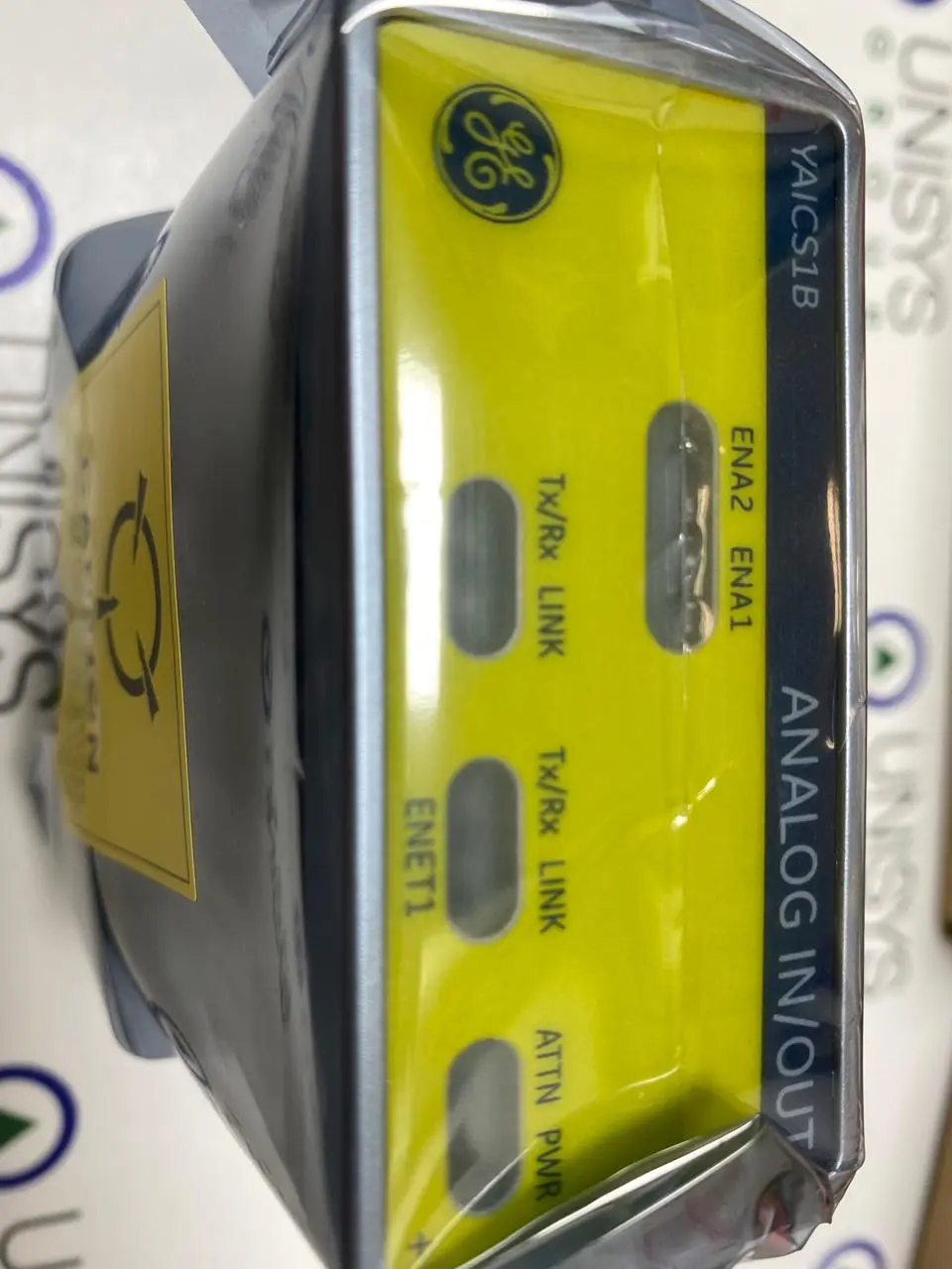
IS420YAICS1B
Module manufactured by General Electric as part of the Mark VI/VIe Series used in gas turbine sppedtronic control systems
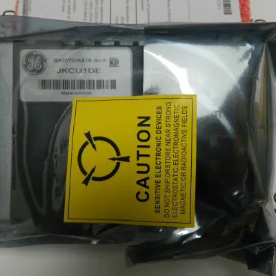
IS420YDIAS1B
Module manufactured by General Electric as part of the Mark VI/VIe Series used in gas turbine sppedtronic control systems
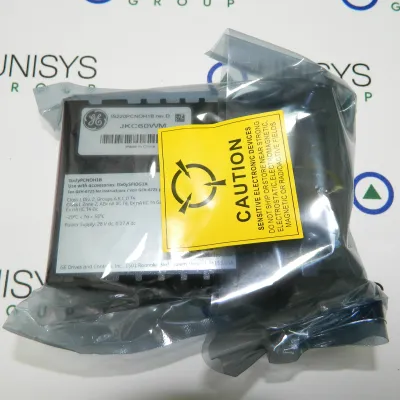
IS220PCNOH1B
Module manufactured by General Electric as part of the Mark VI/VIe Series used in gas turbine sppedtronic control systems
IS210JPDDG3A
Module manufactured by General Electric as part of the Mark VI/VIe Series used in gas turbine sppedtronic control systems
IS200ERGTH1A
Module manufactured by General Electric as part of the Mark VI/VIe Series used in gas turbine sppedtronic control systems
IS400JPDHG1A
Module manufactured by General Electric as part of the Mark VI/VIe Series used in gas turbine sppedtronic control systems
IS420YAICS1B
Module manufactured by General Electric as part of the Mark VI/VIe Series used in gas turbine sppedtronic control systems
IS420YDIAS1B
Module manufactured by General Electric as part of the Mark VI/VIe Series used in gas turbine sppedtronic control systems
IS220PCNOH1B
Module manufactured by General Electric as part of the Mark VI/VIe Series used in gas turbine sppedtronic control systems
IS210JPDDG3A
Module manufactured by General Electric as part of the Mark VI/VIe Series used in gas turbine sppedtronic control systems
IS200ERGTH1A
Module manufactured by General Electric as part of the Mark VI/VIe Series used in gas turbine sppedtronic control systems
IS200EXAMG1B
Module manufactured by General Electric as part of the Mark VI/VIe Series used in gas turbine sppedtronic control systems