Home     GE Turbine Control     GE     IS200STAIS2A

ProductS

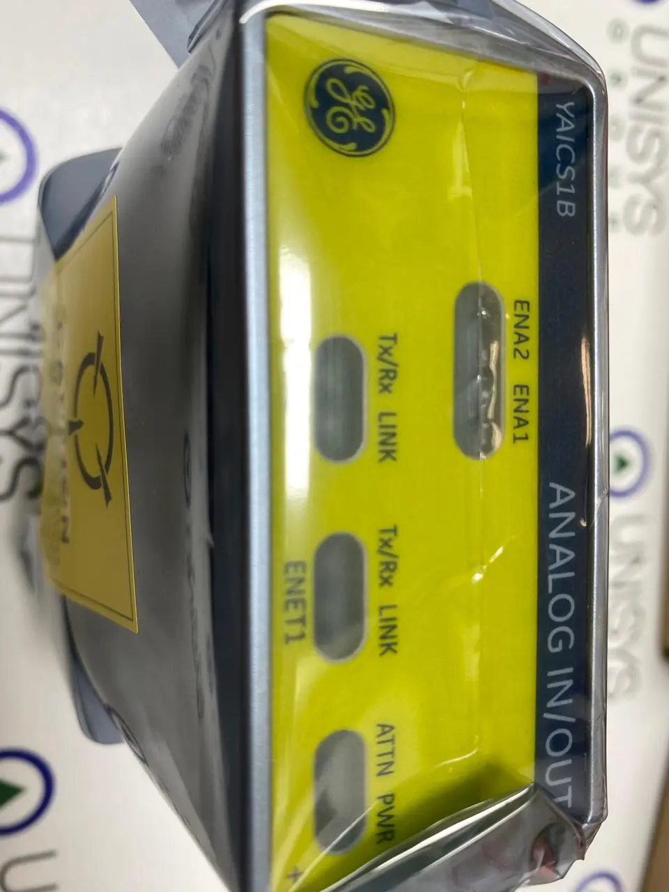
IS200STAIS2A - DINRAIL TRBD ANALOG

4
Module manufactured by General Electric as part of the Mark VI/VIe Series used in gas turbine sppedtronic control systems
Product DESCRIPTION
Part Number
IS200STAIS2A
Manufacturer
General Electric
Country of Manufacture
As Per GE Manufacturing Policy
Series
Mark VI
Function
Module
Availability
In Stock
services we provide
Purchase Icon
Testing & Repair
Repair and Testing of circuit boards to diagnose ensure functionality to maintain current inventory and retain obsolete circuit boards/modules.
Exchange Icon
Training
Controls including HMI Training for Engineers, Technicians and Operators with wide variety of practical equipment including Management and Health & Safety.
Repair Icon
Purchase
You upgrade equipment and we purchase your surplus inventory to maximize the value of unused or end of life assets.
TECHNICAL SPECIFICATIONS FOR GE - IS200STAIS2A

IS200STAIS2A is a Simplex Analog Input terminal board developed by GE under Mark VIe control system. The Simplex Analog Input (STAI) terminal board is a small analog input terminal board that connects to the pack and accepts 10 analog inputs and two analog outputs. The ten analog inputs support two-wire, three-wire, four-wire, and externally powered transmitters. The two analog outputs are 0-20 mA, but one of them can be jumpered to 0-200 mA current. The board is only available in a simplex configuration.

Features

  • High-Density Euro-Block Terminal Blocks: Incorporates high-density Euro-block terminal blocks, which are known for their excellent electrical and mechanical properties. These terminal blocks provide a secure and reliable connection for various input and output signals, facilitating easy and efficient wiring of the system.
  • On-Board ID Chip for System Diagnostics: To enhance system diagnostics and monitoring, the component is equipped with an on-board ID chip. This chip uniquely identifies the board to the system, allowing for easy identification and troubleshooting. It provides essential information about the board's status and configuration, making maintenance and troubleshooting processes more streamlined and effective.
  • Compatibility with PAIC I/O Pack: Fully compatible with the PAIC I/O pack. This compatibility ensures seamless integration between STAI and the PAIC I/O pack, enabling the exchange of data and signals in a smooth and synchronized manner.
  • Ethernet Connectivity: The I/O pack connects to the controller via Ethernet, enabling fast and reliable communication between the I/O pack and the central controller. Ethernet is a widely adopted communication protocol in industrial applications due to its high data transfer rates, low latency, and robustness.
  • D-Type Connector: The pack features a D-type connector for easy and secure connection to the controller. The D-type connector is a standard interface widely used in industrial applications for its reliability and ease of use.
  • Support for Simplex Systems: Specifically designed to support simplex systems. In a simplex configuration, a single controller and I/O pack work together to ensure system operation. This setup simplifies the system architecture and is often used in applications where redundancy is not a critical requirement.
  • Long Cable Length Support: Allows for a maximum two-way cable resistance of 15 ohms and supports cable lengths of up to 300 meters. This feature is beneficial in installations where the I/O pack needs to be located at a significant distance from the controller, without compromising signal integrity and performance.

Installation

During the installation of the STAI (Signal Transmitter Analog Input), several steps and considerations need to be taken into account.

  • The module, along with a plastic insulator, is mounted on a sheet metal carrier. This carrier provides a stable platform for the module and ensures proper alignment. The carrier can be further mounted on a DIN-rail, which offers a standardized method of installation in industrial environments. Alternatively, the STAI module with the insulator can be mounted directly on a sheet metal assembly, securely bolted to a cabinet or other suitable surface.
  • For wiring, it is recommended to use 18 AWG wires, preferably shielded twisted pair cables. These cables are designed to minimize electromagnetic interference and ensure reliable signal transmission. The use of shielded twisted pair cables helps maintain the integrity of analog signals and reduce the risk of noise or signal degradation.
  • The component includes terminal blocks that facilitate the connection of analog inputs and outputs. These terminal blocks serve as interface points for the various types of analog signals supported by the module. Some of the supported analog input types include two-wire transmitters, three-wire transmitters, four-wire transmitters, externally powered transmitters, and voltage inputs with ranges of ±5 V or ±10 V DC. Similarly, the module supports analog output signals in the form of 0-20 mA and 0-200 mA current ranges.
  • To ensure proper grounding and minimize interference, an I/O cable shield terminal is provided. This terminal allows for the connection of shielded cables, which helps protect the analog signals from external electrical noise and disturbances.
  • By following the appropriate installation procedures and utilizing the correct wiring and connections, the STAI module can be successfully integrated into the system, enabling reliable analog signal transmission and processing.

Operation

  • Power Supply: All transmitters connected to the terminal board have access to a 24 V DC power supply. This power supply ensures a consistent and reliable source of power for the transducers or sensors used in the system.
  • Input Selection: By using jumpers, you can select between current and voltage inputs for the STAI module. This flexibility allows compatibility with a wide range of transducers or sensors that provide either current or voltage outputs, depending on the specific requirements of your application.
  • Analog Output Circuits: The STAI module is equipped with two analog output circuits. One circuit operates within the 4-20 mA current range, providing a standardized output signal. The second circuit can be configured, via a jumper, to operate within either the 4-20 mA current range or the broader 0-200 mA range. The selection of the output range depends on the specific application and the compatibility requirements of the receiving devices or systems.
  • Limitations for TMR or TBAI Applications: It's important to note that the terminal board of the STAI module cannot be used for Triple Modular Redundant (TMR) or Terminal Board Analog Input (TBAI) applications. This limitation arises from the presence of only one cable connection on the terminal board, which is insufficient for achieving redundant or expanded input capabilities typically required in TMR or TBAI setups.

Configuration

  • It offers configuration options through the use of jumpers. These jumpers play a crucial role in customizing the functionality of the board according to specific requirements. By referring to the installation diagram, the location of these jumpers can be identified.
  • Jumpers J1A through J8A provide the ability to choose between current or voltage input for the terminal board. This flexibility allows for compatibility with different types of input signals, catering to a wide range of applications.
  • Jumpers J1B through J8B determine whether the return is connected to the common terminal. The common terminal serves as a reference point or ground for the input signals. By adjusting these jumpers, it is possible to establish whether the return is connected to the common terminal or not for each input.
  • For precise input current selection, jumpers J9A and J10A are available. These jumpers allow you to choose between an input current of 1 mA or 20 mA, depending on the specific requirements of the system.
  • Additionally, jumpers J9B and J10B also impact the connection of the return to the common terminal, providing further control over the circuit configuration.
  • Among the available jumpers, J0 serves a unique purpose. Jumper J0 allows the selection of either 20 mA or 200 mA for output 1, providing the necessary flexibility to adapt the terminal board's output to the desired specifications.

Diagnostics

  • The board incorporates diagnostic tests on the terminal board to ensure proper functionality and identify potential issues. These diagnostic tests involve specific mechanisms and devices that enable the board to detect and report faults or hardware incompatibilities. The diagnostic procedures are as follows:
    • Voltage Drop Test: The board utilizes a series resistor to measure the voltage drop across it, providing an indication of the output current. By monitoring the voltage drop, the board's I/O processor can assess the health of the outputs. If any one of the two outputs deviates from the expected values or becomes unhealthy, the I/O processor generates a diagnostic alarm or fault. This fault alert notifies users or system administrators that there is a potential issue with the outputs, enabling them to take appropriate actions to rectify the problem.
    • Cable Connector ID Device: Each cable connector present on the terminal board is equipped with its own ID device. This ID device is an integrated chip that contains essential information, including the terminal board's serial number, board type, revision number, and the location of the connector (JR, JS, JT). The ID device is a read-only chip, meaning it can be interrogated by the board's I/O controller to retrieve the encoded information.

  • During the diagnostic process, the I/O controller reads the information from the ID device of each cable connector. It compares this information with the expected values, which are typically pre-programmed or stored within the system. If a mismatch or inconsistency is detected between the read data and the expected values, it indicates a hardware incompatibility between the terminal board and the connected cables. In such cases, the I/O controller generates a hardware incompatibility fault, indicating that there is a mismatch between the terminal board and the connected cables.
  • The hardware incompatibility fault serves as an alert to users or technicians, informing them that the current terminal board configuration and the connected cables may not be compatible. This enables them to address the issue by ensuring the correct cables are used or making the necessary adjustments to achieve compatibility.
  • By incorporating these diagnostic tests, it provides mechanisms to detect potential faults and hardware incompatibilities. These diagnostic procedures enable the board to monitor and assess the health of its outputs and verify the compatibility of the terminal board with the connected cables. The generated diagnostic alarms and hardware incompatibility faults serve as valuable information for troubleshooting and maintenance, aiding in the prompt identification and resolution of any potential issues encountered during the operation of the board.
featured products