Home     GE Turbine Control     GE     IS220PAICH1B

ProductS

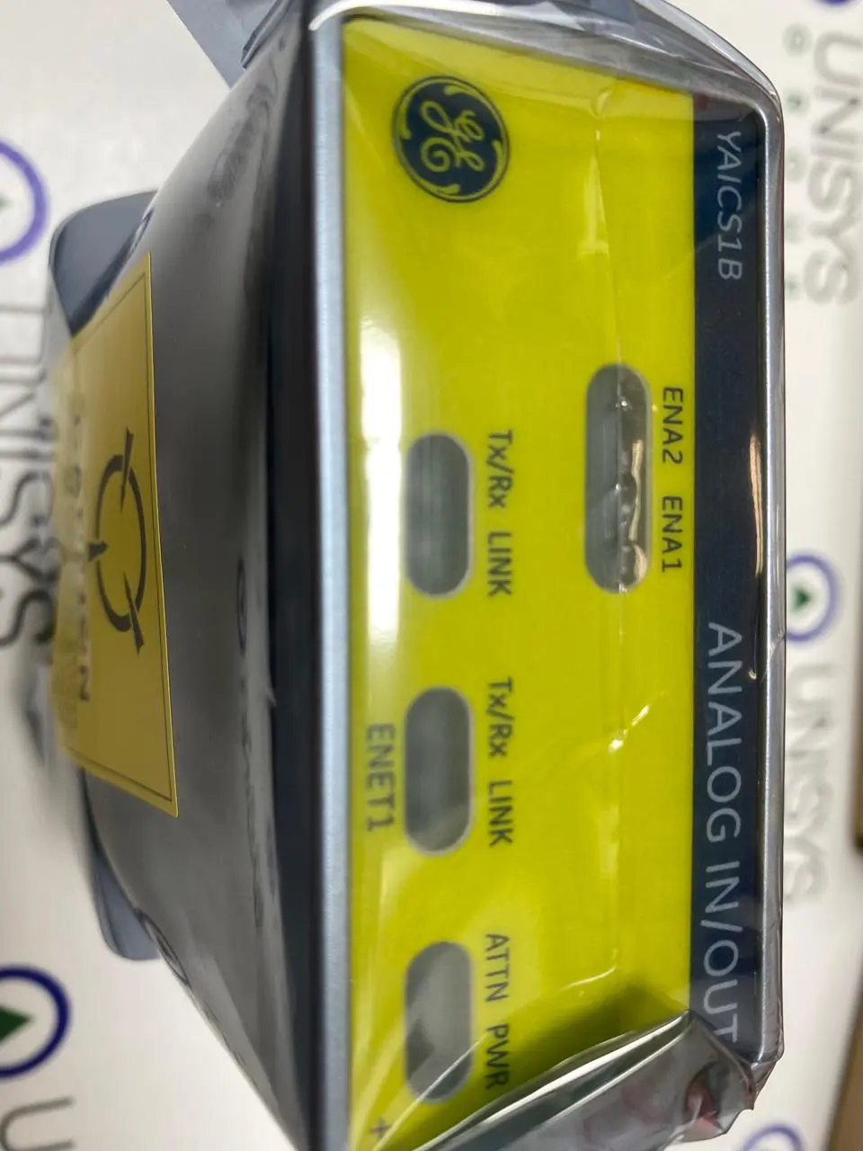
IS220PAICH1B - IO PACK ANALOG IN/OUT BASIC

4
Module manufactured by General Electric as part of the Mark VI/VIe Series used in gas turbine sppedtronic control systems
Product DESCRIPTION
Part Number
IS220PAICH1B
Manufacturer
General Electric
Country of Manufacture
As Per GE Manufacturing Policy
Series
Mark VIe
Function
Module
Availability
In Stock
services we provide
Purchase Icon
Testing & Repair
Repair and Testing of circuit boards to diagnose ensure functionality to maintain current inventory and retain obsolete circuit boards/modules.
Exchange Icon
Training
Controls including HMI Training for Engineers, Technicians and Operators with wide variety of practical equipment including Management and Health & Safety.
Repair Icon
Purchase
You upgrade equipment and we purchase your surplus inventory to maximize the value of unused or end of life assets.
TECHNICAL SPECIFICATIONS FOR GE - IS220PAICH1B

The IS220PAICH1B is a GE Analog I/O pack from the Mark VIe series. The PAIC pack serves as the electrical interface between one or two I/O Ethernet networks and an analog input terminal board. The pack includes a processor board shared by all Mark VIe distributed I/O packs and an acquisition board dedicated to the analog input function.

IS220PAICH1B Functional Description

  • The pack can handle up to ten analog inputs, the first eight of which can be configured as 5 V or 10 V inputs or 0-20 mA current loop inputs. The last two inputs can be set to 1 mA or 0-20 mA current inputs.
  • The load terminal resistors for the current loop inputs are located on the terminal board, and the PAIC senses voltage across these resistors. The PAICH1 also has two 0-20 mA current loop outputs. The PAICH2 includes additional hardware to support 0-200 mA current on the first output.
  • The pack is powered by a three-pin power input and two RJ45 Ethernet connectors. Output is via a DC-37 pin connector that is directly connected to the associated terminal board connector. LED indicator lights provide visual diagnostics.

Processor features

  • The processor board is linked to an acquisition board dedicated to the function of the I/O pack or module. When input power is applied, the soft-start circuit increases the voltage available on the processor board. The local power supplies are turned on in sequence, and the processor reset is disabled.
  • After finishing self-test routines, the processor loads application code specific to the I/O pack or module type from flash memory. The application code reads board ID information to ensure that the application code, acquisition board, and terminal board are all correctly matched.

Auto-Reconfiguration

  • The Auto-Reconfiguration feature allows the operator to replace I/O packs without having to manually reconfigure each pack or module.
  • When the controller detects an I/O pack booting with a different configuration and the Auto-Reconfiguration feature is enabled, a reconfiguration file is automatically downloaded from the controller to the I/O pack. The bootload, baseload, firmware, and parameters are all reconfigured.
  • Unless it already has the latest version, each I/O pack is updated with the current configuration that matches the configuration used by the controller.

Analog Input Hardware

  • For all ten input channels, the PAIC accepts input voltage signals from the terminal board. An analog multiplexer block, several gain and scaling options, and a 16-bit analog-to-digital converter comprise the analog input section (DAC).
  • Depending on the input configuration, the inputs can be configured as 5 V or 10 V scale signals. When configured for current inputs, the terminal board includes a 250 burden resistor that produces a 5 V signal at 20 mA.

Analog Output Hardware

  • The PAIC has two 0-20 mA analog outputs that can operate at 18 V compliance in simplex or TMR mode. A 14-bit DAC sends a current reference to the PAIC's current regulator loop, which detects current in both the PAIC pack and the terminal board.
  • Each analog output circuit also includes a normally open mechanical relay for enabling or disabling output operation. The relay is used in a TMR system to remove a failed output, allowing the remaining two PAICs to create the correct output without interference from the failed circuit.
  • When the suicide relay is deactivated, the output opens through the relay, short-circuiting the PAIC's analog output from the terminal board's customer load.
featured products