TECHNICAL SPECIFICATIONS FOR GE - IS230PCAAH1B
IS230PCAAH1B is a Core Analog I/O Module manufactured and designed by General Electric as part of the Mark VIe Series used in distributed control systems. A sizable amount of the analog signal I/O needed to run a gas turbine is provided by the Core Analog (PCAA) module and related Core Analog (TCAS and TCAT) terminal board. Thermocouple, 4-20 mA current loop, seismic, linear variable differential transformer (LVDT) excitation and inputs, pulse rate, and servo coil outputs are all provided by PCAA and TCAT. In simplex, dual, and TMR systems, PCAA is applicable. To one, two, or three linked PCAA modules, a single TCAT terminal board fans signal inputs. In addition to the terminals on PCAA and TCAT, a nearby JGPA board also has shield ground and 24 V field power connectors.
Two application I/O boards, a terminal board, and a processor board that is shared by all Mark* VIe distributed I/O are all included in PCAA. The various boards that make up the module are not supported for diagnosis or replacement, making the entire module the least changeable component.
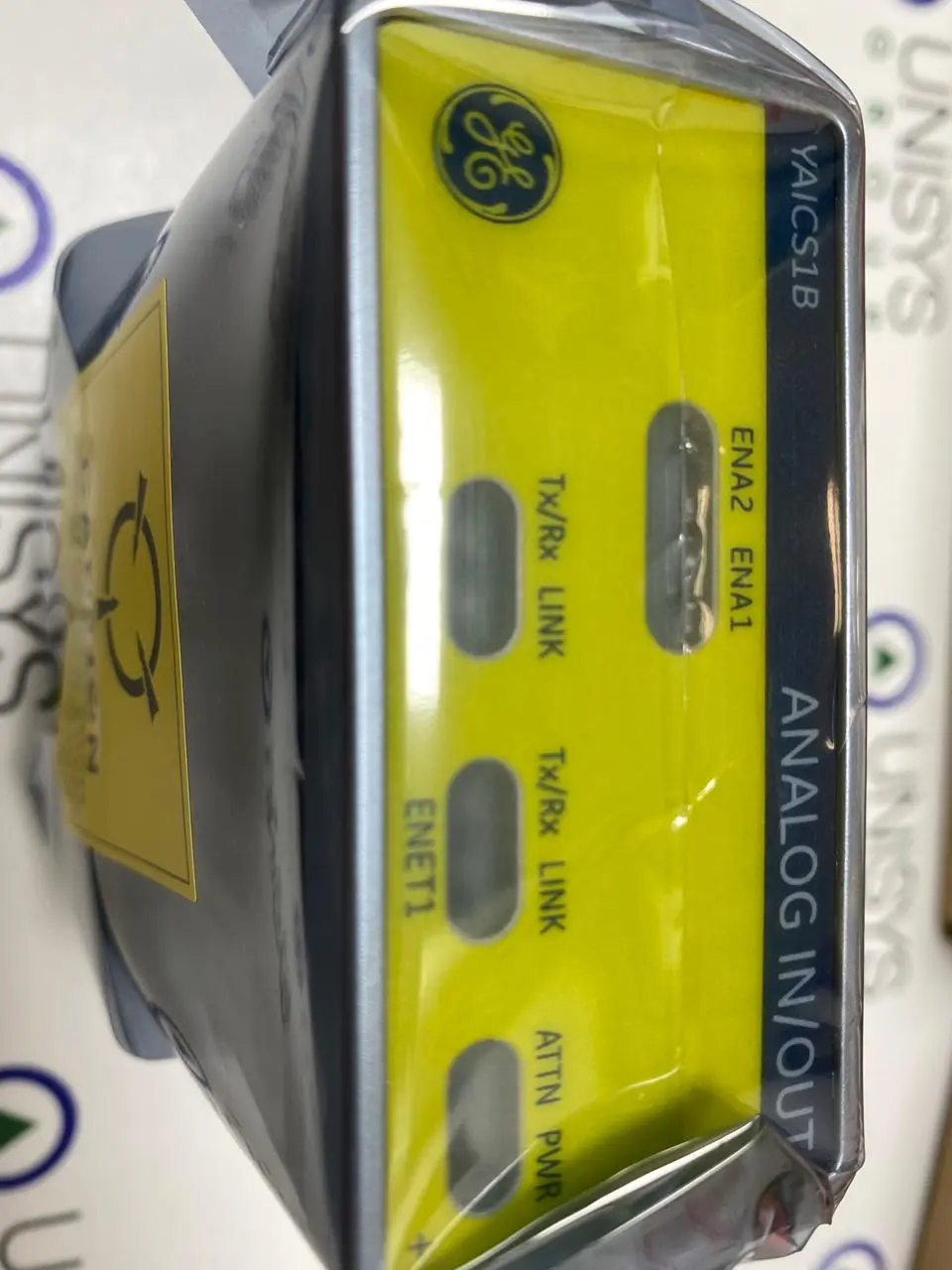
Dual RJ45 Ethernet connectors and the 28 V dc power connector P5 are used to supply the module with input. 120 box terminals in the Euro style are located on the module edge and are used for field device I/O. Connector P4 provides power to a JGPA board. Two 68-pin cables on connectors P1 and P2 are used to connect the module to the TCAT.
PCAA divides the signals into two categories. The TCAT terminal board is used to route signal inputs that can be fanned from a single input into a single, dual, or TMR PCAA module. The terminals of PCAA are wired with signals that are exclusive to a single PCAA module. As a result, the signal split in the following table is produced. If the fanned inputs are not necessary, PCAA can be used in place of TCAT.
Each Mark VIe I/O pack and controller is fully compatible with the PCAA module. The following table lists the frame rates, redundancy, and networking that PCAA supports.
INSTALLATION:
Mount the PCA A module firmly.
Attach the P4 connector on the PCAA to the JGPA power connection.
Attach two 68-pin cables to connectors P1 and P2 on a TCAT terminal board that is optionally coupled with the PCAA module. A network connection pairs the connectors on TCAT. PS1 and PS2 connect to a PCAA that is part of the S controller network, PT1, and PT2 connect to a PCAA that is part of the T controller network, and PR1 and PR2 connect to a PCAA that is part of the R controller network.
To maintain adequate cable grounding, it is crucial to just finger-tighten the mounting screws into PCAA and TCAT. If the wires are not secured, PCAA may be unable to read the electronic ID on TCAT, which could degrade other communications.
Depending on the setup of the machine, connect either one or two Ethernet wires. The module works properly over either port when a single IONet connection is utilized. The R controller's network should be connected to ENET1 if dual connections are being used.
The PCAA, however, does not care how an Ethernet connection is made and negotiates correct functionality via either port. The network connection should match the connection made to TCAT if TMR PCAA modules are present. For instance, cables to the TCAT PR1 and PR2 connectors should be present on the PCAA module with the R IONet connection.
Verify that the JGPA shield wire terminals are grounded. The JGPA shield ground connections are typically electrically connected to the sheet metal that the board is mounted on. The ground path for the terminals is then provided by the mounting.
It may be necessary for some situations to specify a shield ground that is separate from the mounting sheet metal. The JGPA is mounted in these applications utilizing hardware that separates the board from the sheet metal. Between one or more JGPA terminals and the necessary shield ground potential in these applications, a suitable ground wire must be provided.
Check the power and Ethernet status indicator lights after powering on the module using the P5 connector.
OPERATION:
The PCAA module is a physical assembly made up of four different circuit boards. Because it is challenging to narrow down a failure to a specific board, the module is thought of as the least replaceable component. Individual boards cannot be replaced with the module.
Each Mark VIe Ethernet I/O pack or module shares a processing board. It has the following in it:
A quick processor with RAM and flash memory is number one.
Two plugs for entirely independent 10/100 Ethernet ports
Hardware reset and watchdog timer circuit
A sensor for internal temperature
LEDs that indicate the status
The capacity to read IDs on other boards and electronic identification
An input power connector with a current limiter and a gentle start
Local power supplies, which also include monitoring and sequencing
At frame rates of 40 and 10 ms, the PCAA module is intended to operate. Each signal type has a list of accuracy requirements that take into account all factors, including aging, temperature, power supply input change, and product variance. It also lists the mean and standard deviation for each signal type's typical accuracy at 25 C. The specified accuracy is the ultimate worst-case limit on the signal accuracy, but the usual accuracy is comparable to the precision that may be anticipated in regular operation.